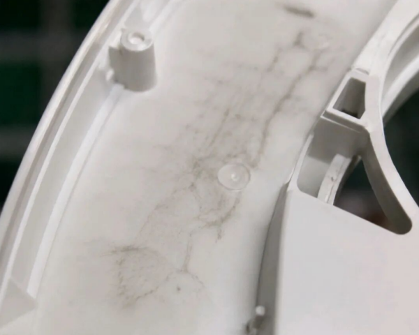
3 défauts critiques cachés à l'intérieur des pièces en plastique à paroi épaisse fortement chargées
Plastiques fortement chargés en fibres de verre et en minéraux sont largement utilisés dans les applications structurelles automobiles, électroménagères et industrielles car ils offrent une excellente rigidité, résistance et stabilité dimensionnelle.
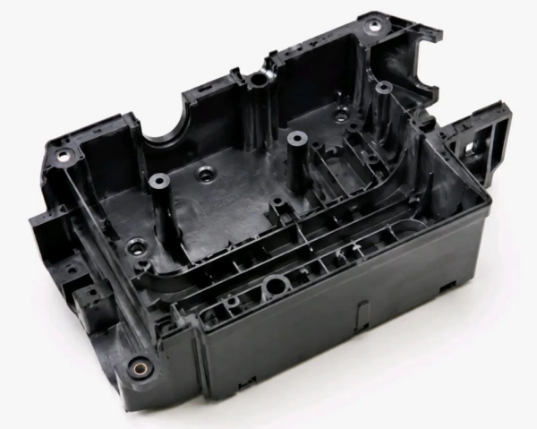
Cependant, les composants moulés à paroi épaisse fabriqués à partir de plastiques fortement chargés sont très sensibles aux défauts internes cachés, notamment les vides internes, le délaminage et les bouchons froids.
Comme ces défauts sont cachés sous la surface, ils ne peuvent souvent pas être détectés par une inspection visuelle normale. Lors du fonctionnement réel, les défauts internes peuvent devenir des zones de concentration de contraintes, provoquant des fissures, des fuites, des défaillances soudaines et des rejets de lots coûteux.
Table des matières
-
Pourquoi les pièces en plastique à paroi épaisse fortement chargées sont-elles plus sujettes aux défauts internes ?
-
Vides internes / cavités de retrait
-
Délaminage / séparation entre couches
-
Bouchons froids / taches sombres internes
1. Pourquoi les pièces en plastique à paroi épaisse fortement chargées sont-elles plus sujettes aux défauts internes ?
Comparés aux plastiques fortement chargés, les plastiques conventionnels non chargés présentent généralement une meilleure fluidité et un comportement de retrait plus uniforme, ce qui entraîne moins de risques de moulage.
Cependant, après l'ajout de grandes quantités de fibres de verre ou de charges minérales, la viscosité de la matière fondue augmente considérablement. Le matériau devient plus difficile à faire s'écouler, à remplir et à compacter lors du moulage par injection.
Deux défis majeurs des structures à paroi épaisse
1. Chemins d'écoulement plus longs et refroidissement inégal
Lors du moulage par injection, le plastique fondu en contact avec la surface plus froide du moule se solidifie en premier, formant une peau extérieure durcie. Pendant ce temps, le matériau interne refroidit beaucoup plus lentement, créant une grande différence de température entre la surface et le cœur.
2. Retrait de refroidissement plus important dans les sections épaisses
Les sections épaisses subissent un retrait volumique plus important pendant le refroidissement. Le maintien d'une pression de compactage suffisante et l'obtention d'une fusion uniforme du matériau deviennent beaucoup plus difficiles.
Lorsque l'écoulement de la matière fondue, le transfert thermique ou la liaison moléculaire devient déséquilibré, des défauts internes cachés peuvent se former à l'intérieur du composant.
Ces défauts sont souvent invisibles lors d'une inspection visuelle conventionnelle et nécessitent généralement une analyse destructive par coupe ou des méthodes d'inspection avancées non destructives telles que la tomographie CT.
2. Vides internes / cavités de retrait : zones creuses cachées à l'intérieur des pièces structurelles
1. Caractéristiques du défaut
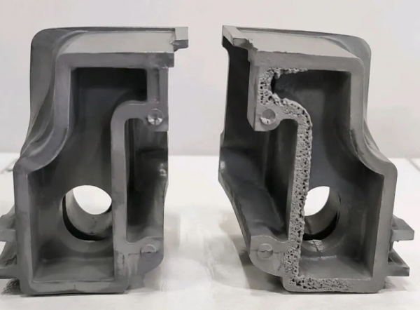
La surface extérieure du composant peut sembler complètement normale sans défauts visibles. Cependant, après découpe de la section à paroi épaisse, des vides internes ou des cavités irrégulières peuvent être observés.
Ces vides internes réduisent la zone porteuse effective et affaiblissent considérablement les performances structurelles. Sous contrainte mécanique, les composants peuvent se fissurer ou se rompre, tandis que les pièces d'étanchéité peuvent présenter des problèmes de fuite.
2. Mécanisme de formation
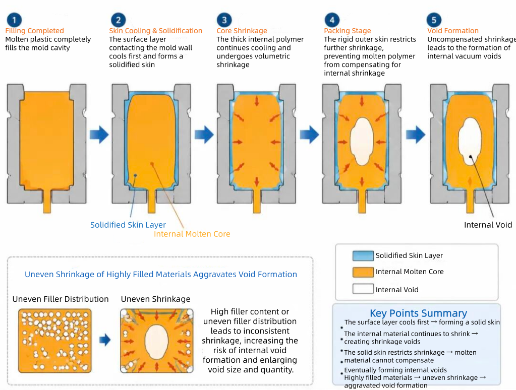
Après que le plastique fondu a complètement rempli la cavité du moule, le matériau en contact avec la paroi du moule refroidit et se solidifie en premier, créant une coque extérieure rigide.
Le plastique fondu interne continue à refroidir et à se rétracter. Cependant, la couche extérieure durcie limite la contraction supplémentaire.
Pendant l'étape de compactage, une quantité insuffisante de matière fondue est disponible pour compenser le retrait, formant finalement des vides internes sous vide.
Pour les matériaux fortement chargés, le retrait inégal entre la matrice polymère et les charges peut encore augmenter le risque de formation de vides.
3. Causes principales
-
Épaisseur locale excessive de la paroi ou transitions brusques d'épaisseur.
-
Taux de retrait élevé du matériau.
-
Pression d'injection ou pression de compactage insuffisante.
-
Position du point d'injection trop éloignée des zones à paroi épaisse.
-
Mauvaise évacuation de l'air du moule ou conception incorrecte des canaux de refroidissement.
4. Solutions d'amélioration
① Optimisation de la conception de la pièce
-
Maintenir une épaisseur de paroi uniforme sur l'ensemble du composant.
- Ajoutez des structures creuses, des nervures ou des caractéristiques de réduction de matière dans les zones épaisses afin de réduire l'accumulation excessive de matière.
② Optimisation de la sélection des matériaux
- Sélectionnez des plastiques fortement chargés présentant un faible retrait et une bonne fluidité.
- Assurez une dispersion uniforme des charges afin d'améliorer la stabilité dimensionnelle et de réduire les contraintes internes.
③ Optimisation du processus de moulage par injection
- Augmentez la température de fusion et la température du moule afin de ralentir la solidification prématurée de la surface.
- Prolongez le temps de maintien et appliquez une pression de maintien à plusieurs étapes afin de fournir une compensation continue de matière pendant le retrait au refroidissement.
④ Optimisation de la conception du moule
- Positionnez le point d'injection plus près des zones à paroi épaisse afin de raccourcir les chemins d'écoulement et de réduire les pertes de pression.
- Ajoutez des canaux d'éventilation près des sections épaisses afin d'améliorer l'évacuation des gaz.
- Appliquez des canaux de refroidissement conformes afin d'obtenir une distribution plus uniforme de la température du moule.
3. Délamination / Séparation inter-couche : des couches cachées qui réduisent considérablement la résistance mécanique
1. Caractéristiques du défaut
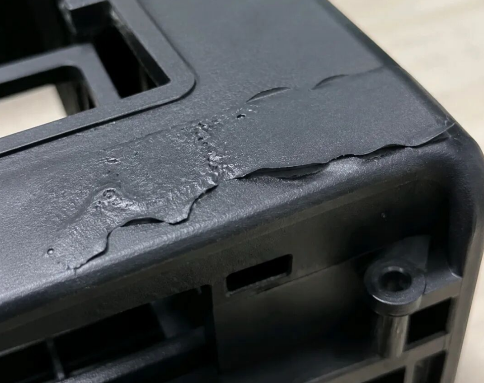
Une inspection en coupe transversale révèle des motifs stratifiés nets, indiquant que les couches de matériau n'ont pas réussi à fusionner correctement entre elles.
Les couches peuvent se séparer facilement le long de l'interface faible, même sous une contrainte mécanique relativement faible.
Ce défaut entraîne une réduction significative de la résistance aux chocs et de la résistance à la flexion, ce qui en fait l'un des défauts internes les plus graves des composants structurels en plastique.
2. Mécanisme de formation
Les plastiques fortement chargés présentent une viscosité de fusion plus élevée et une moins bonne fluidité par rapport aux matériaux non chargés. Lors du remplissage du moule, la matière fondue peut se diviser en plusieurs fronts d'écoulement.
Lorsque différents flux de matière fondue présentant des températures et des vitesses d'écoulement différentes se rencontrent, les chaînes de polymère peuvent ne pas réussir à s'interpénétrer et à fusionner correctement.
Après refroidissement, une couche de séparation permanente se forme à l'intérieur de la pièce.
Des vitesses d'injection élevées peuvent générer des effets de jet et un écoulement instable dans la cavité, tandis que le reflux de matière fondue pendant le remplissage peut accentuer davantage la délamination.
3. Causes principales
- La température de fusion et la température du moule sont trop basses, ce qui entraîne une mauvaise fluidité du matériau.
- Plusieurs points d'injection créent des fronts d'écoulement séparés avec des angles de fusion excessifs.
- La vitesse d'injection est trop élevée, provoquant des défauts de jet.
- Un séchage insuffisant des matériaux plastiques permet à l'humidité d'empêcher une fusion correcte entre les couches de matière fondue.
4. Solutions d'amélioration
① Augmenter la température pour améliorer la fluidité
- Augmentez à la fois la température du cylindre et la température du moule afin de réduire la viscosité de la matière fondue et de favoriser une meilleure fusion entre les fronts d'écoulement.
② Optimiser la conception du canal d'alimentation et du point d'injection du moule
- Réduisez le nombre de points d'injection lorsque cela est possible.
- Minimisez l'angle entre les flux de matière fondue convergents.
- Concevez des transitions de canaux d'alimentation lisses afin d'éviter les effets de jet et les comportements de remplissage instables.
③ Ajuster les paramètres d'injection
- Appliquez une injection en plusieurs étapes avec un remplissage contrôlé à faible vitesse dans les zones critiques.
- Évitez les effets de jet et empêchez le reflux instable de matière fondue pendant le remplissage.
④ Améliorer la préparation des matériaux
- Séchez soigneusement les matières premières avant le moulage afin d'éliminer l'humidité.
- Prolongez correctement l'étape de maintien et utilisez une pression de maintien afin d'améliorer la liaison entre les couches.
4. Masselottes froides / Taches sombres internes : défauts d'apparence combinés à des zones cachées de concentration de contraintes
1. Caractéristiques des défauts
Des stries et des taches sombres, ternes ou mates peuvent apparaître à la surface ou à l'intérieur du composant.
Ces défauts sont généralement causés par une répartition irrégulière du renfort, un écoulement instable de la matière fondue ou une fusion insuffisante entre différentes zones de matériau.
En plus d'affecter l'apparence, ces zones présentent souvent une résistance de liaison plus faible et deviennent des zones potentielles de concentration des contraintes, réduisant ainsi la fiabilité globale du composant.
2. Mécanisme de formation
Une partie de matériau à basse température accumulée dans le système de canaux ou à l'extrémité avant du fourreau peut entrer dans l'empreinte du moule avec l'écoulement normal du plastique fondu.
Comme le matériau froid et la matière fondue chaude présentent des différences importantes de température et de viscosité, une fusion complète ne peut pas être obtenue.
Le bouchon froid reste piégé à l'intérieur ou près de la surface de la pièce moulée, créant des taches de couleur sombre ou des marques irrégulières.
Pour les composants à parois épaisses, l'écoulement de la matière fondue se divise souvent en plusieurs flux, augmentant la possibilité que le matériau froid soit piégé et forme des défauts internes.
3. Causes courantes
- La température de fusion ou la température du moule est trop basse.
- La vitesse d'injection est trop lente, ce qui permet au front de matière fondue de refroidir prématurément.
- Une ramification excessive des canaux augmente les zones inutiles de convergence de la matière fondue.
- Une mauvaise évacuation de l'air provoque un gaz emprisonné autour des zones de matériau froid.
4. Solutions d'amélioration
① Augmenter la température pour réduire les différences thermiques
- Augmenter la température du fourreau et la température du moule afin d'améliorer les conditions de fusion et de favoriser une meilleure fusion.
② Optimiser la vitesse d'injection
- Augmenter la vitesse d'injection de manière appropriée afin de réduire le temps de remplissage et de limiter le refroidissement prématuré du front de matière fondue.
③ Améliorer la conception du moule
- Simplifier les systèmes de canaux afin de réduire les points inutiles de fusion des flux.
- Ajouter des puits de récupération des bouchons froids pour capturer le matériau à basse température avant son entrée dans les zones critiques.
④ Optimisation supplémentaire
- Améliorer l'évacuation de l'air dans les zones de convergence des flux de matière fondue.
- Ajouter des modificateurs d'écoulement appropriés lorsque cela est nécessaire afin d'améliorer la compatibilité de la matière fondue et les performances de transformation.
Conclusion : La prévention des défauts internes nécessite une optimisation des matériaux, du procédé et du moule
Pour les composants plastiques à parois épaisses fortement chargés, les défauts internes sont souvent invisibles lors des inspections conventionnelles mais peuvent affecter gravement la fiabilité à long terme, les performances mécaniques et la sécurité du produit.
Une solution efficace nécessite une optimisation complète de la sélection des matériaux, de la conception des pièces, des paramètres de moulage par injection et de la structure du moule.
En sélectionnant des thermoplastiques renforcés haute performance à retrait contrôlé, en optimisant les conditions de transformation et en améliorant la conception du moule, les fabricants peuvent réduire considérablement les risques de vides, de délamination et de défauts liés aux bouchons froids.
Pour les applications structurelles légères et les projets de remplacement du métal, le contrôle de la qualité interne est essentiel pour obtenir des performances stables et une production fiable.
Questions fréquemment posées sur les défauts des plastiques fortement chargés
Pourquoi les plastiques renforcés de fibres de verre développent-ils des vides internes ?
Les vides internes apparaissent généralement parce que les sections épaisses subissent un retrait de refroidissement irrégulier. Lorsque la surface extérieure se solidifie avant le cœur, une compensation de compactage insuffisante peut créer des cavités internes.
Les défauts internes des pièces moulées par injection peuvent-ils être détectés visuellement ?
Non. De nombreux défauts internes tels que les vides et la délamination sont cachés sous la surface et ne peuvent pas être identifiés par une inspection visuelle normale. Des méthodes d'inspection avancées telles que la tomodensitométrie ou l'analyse par coupe sont souvent nécessaires.
Comment les thermoplastiques renforcés de fibres longues peuvent-ils améliorer la fiabilité structurelle ?
Les thermoplastiques renforcés de fibres longues offrent un meilleur transfert de charge, une résistance aux chocs plus élevée, une meilleure stabilité dimensionnelle et une réduction du gauchissement par rapport aux matériaux conventionnels renforcés de fibres courtes.
Besoin de matériaux fiables pour des composants structurels à parois épaisses ?
Les pièces en plastique fortement chargées nécessitent plus qu'une simple augmentation de la teneur en charge. La conservation de la longueur des fibres, la dispersion des charges, le contrôle du retrait et la stabilité du procédé sont des facteurs essentiels pour obtenir des performances structurelles fiables.
LFT-G développe des solutions en thermoplastiques renforcés de fibres longues, notamment PP-LGF, PA-LGF, PA-LCF, PPS-LGF et d'autres composites haute performance pour les applications automobiles, industrielles, électroménagères et structurelles légères.
Explorer les matériaux LFT-G

 email
email français
 English
 Deutsch
 русский
 italiano
 español
 português
 العربية
 日本語
日本語 한국의
한국의 中文
中文